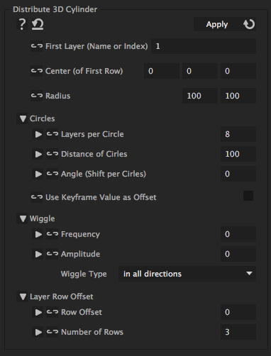
Distribute 3D Cylinder
With this iExpression you can distribute 3D layers on the surface of a cylinder. The layers are placed on circles around the clyinder surface and you can specify how many layers each circle should consist of and what distance the different circles should have. You can still move layers away from their position on the cylinder using their keyframe values or the wiggle parameters. In order to orient the layers correctly on the cylinder surface, apply the "Look At Line 3D" iExpression to their orientation and choose as first point of the line the center of the sphere and as second point an arbitrary point exactly above or below it (e.g. the center with a value of 100 added to its y value). If you want to move or rotate the cylinder, its best to set the center to (0,0,0), then create a new NULL object, make it 3D and parent the layers on the cylinder surface to this NULL. During the parenting keep the alt or option key pressed. Then the position of the NULL becomes the center of the cylinder and you can move or rotate it using the transform controls of the NULL.
First Layer (Name or Index)
is the name or index of the first layer that should be placed on the cylinder.
Center (of First Row)
is the center of the cylinder at the height of the first circle of layers. All subsequent circles are placed below the first one.
Radius
is the radius of the cylinder. If the x and y component are not idendical, the cylinder does not look like a circle from the top, but like an ellipse.
Circles
Layers per Circle
denotes how many layers should be placed in one circle around the cylinder surface before the next circle (which is placed below) is started.
Distance of Cirles
denotes the distance between the different circles on which the layers are placed on the cylinder surface.
Angle (Shift per Cirles)
allows to palce the layers on the second circle not exactly below the layers in the first circle but shifted by the given angle.
Use Keyframe Value as Offset
allows to move each layer away from its position on the cylinder surface using keyframes. In order to be exactly placed at its position on the cylinder, a layer then must have the keyframed position (0,0,0). If the position is different, the difference is used as an offset to the position on the cylinder surface.
Wiggle
Frequency
makes the layer wiggle around its position on the cylinder surface with the given frequency. If you don't want it to move at all, set the frequency to 0.
Amplitude
denotes up to how much the layer may move away from its position on the cylinder surface. To create a little less regular but still not moving placement of the layers, set the frequency to 0 and the amplitude to some value greater 0.
Wiggle Type
determines in which way the layers are wiggled. 'in all directions' moves the layers arbitrarily in 3D space (also away from the clyinder surface), 'on surface left/right/up/down' moves the layers in arbitrary directions on the surface of the cylinder , and 'on surface left/right' moves them only along the circles around the cylinder surface on which they are placed.
Layer Row Offset
Row Offset
with an offset of one, the first row of layers is removed from the top and added again at the bottom below the last row. For an offset of 2 this happens for the first two rows of layers etc.
Number of Rows
denotes how many rows of layers around the cylinder exist. A value of 3 means, for example, that the first row is moved below the third row if there is a row offset.
Download at aescripts.com